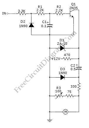
Tachometer Circuit with Single Transistor

A schematic diagram of simple tachometer circuit is shown below. Using only a single transistor as the active component, this tachometer would probably be the simplest one. The input of this circuit can be picked up from ignition pickup coil, or other wiring that gives ignition wave-form. This tachometer circuit works for 0 to 6,000 rpm. R3 is used for calibrating the full scale meter reading, to get valid rpm. The zener diode D1 is used to stabilize the 12-V supply. Here is the schematic diagram of the circuit:
