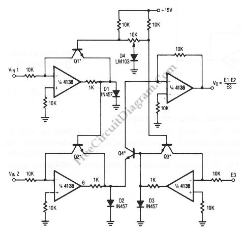
This unique circuit below can be used as divider and multiplier. This circuit is formed by all four sections of a 4136 . The Q1 through Q4 can be any PNP transistor, but that must matched transistors. The transistor matching determine the acurracy of the divider and multiplier circuit. Here is the schematic diagram of the circuit:

Analog multiplier divider circuit schematic


Possibly Related Articles:

  • Infinite Resolution Frequency Multiplier/Divider
    Normally, frequency multiplier or divider has only discrete ratio operation since it uses digital divider as the main process for division or multiplication. By first converting the incoming frequency into...
  • Analog Multiplier
    The figure below shows a simple embodiment of the analog multiplier. This circuit provides three quadrant analog multiplication which is relatively temperature insensitive and which is not subject to the...
  • Single Chip Divider Circuit
    We can build a divider circuit using only a single chip component, a special purpose integrated circuit AD532. We can configure the AD532 as a two quadrant divider by connecting...
  • AD532 Multiplier IC and Its Pin Configurations
    The AD532 is the first pre-trimmed single chip monolithic multiplier/divider. This device guarantees a maximum multiplying error of +- 1% and a +-10 V output voltage without the need for...
  • Two Op-Amps Instrumentation Amplifier
    For standard instrumentation amplifier, a three op-amps instrumentation amplifier circuit is common, but if you need smaller component count and lower cost, you can use just two op-amps for the...
  • Three Op-Amps Instrumentation Amplifier
    Using LMV721/722 or any other high impedance op-amps, you can build an instrumentation amplifier using standard three op-amps instrumentation amplifier circuit. The figure below shows the circuit’s schematic diagram. The...
  • Function Generator Using CA3080 and CA3130 Op-Amps
    The schematic diagram shown in the figure below show a function generator circuit using CA3130 in the integrator the threshold detection sections. Both triangular and square-wave signal are available from...
  • Difference Of Squares Analog Computing
    Because the differential input capability of the AD532, algebraic solution of several interesting functions such as difference of squares, (X2-Y2)/10V is allowed. The following figure shows us about the configuration...
  • Pulse Width to Analog Voltage Demodulator
    This is a schematic diagram of a pulse width to analog demodulator circuit. This circuit is used to demodulate the pulse width to analog voltage level. With input pulse width...
  • Three Op-Amps Instrumentation Amplifier: Easy Gain Adjustment Design
    Although this circuit use more resistor components than in basic standard three op-amps instrumentation amplifier circuit, this circuit has the benefit of easy gain adjustment with only one control resistor....
  • Square Root Mode for AD532 Analog Processor
    The following schematic diagram shows us about the connections for square root mode for ADS532 analog processor chip.  Similar to the division mode, the multiplier cell is connected in the...
  • Voltage Divider – Video Tutorial
    This is a voltage divider video tutorial. This video explains about the voltage divider and the use of voltage divider. Voltage divider is the circuit that is used to reduce...