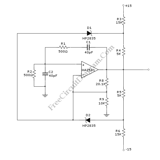
A Wien-Bridge oscillator circuit can be built from HA2541 and some basic components. This circuit can generate good-quality sine wave of 40 MHz with an upper limit of 50 MHz. The R3 through R7 and D2 and D1 provide the diode limiting for this circuit. Here is the schematic diagram of this circuit:

Wien Bridge Oscillator circuit schematic
For frequency stability, this circuit need a regenerative feedback. The feedback network is formed by R2/C2 and R1/C1. To obtain the oscillation, the gain required is three but practically we need gain over three.  So R9 and R8 is added to this circuit to provide gain over three times.


Possibly Related Articles:

  • Wien-Bridge Oscillator Using Incandescent lamp Stabilizer
    Incandescent lamp has been used to reduce harmonic distortion in sine oscillator circuit. The nonlinear resistance characteristic of the lamp filament help the circuit to shape the signal to approximate...
  • Wien Bridge Oscillator: The Circuit Schematic Diagram and The Design Formula
    The excellent high input impedance, high slew rate, and high voltage qualities of CA3140 op-amp make it suitable for Wien-bridge sine wave oscillator. The basic circuit for Wien-bridge sine wave...
  • Low Distortion Oscillator
    With very low harmonic distortion, 2N4416 JFET is suitable to smoothly oscillate in a circuit. On application where low harmonic content is required for a good mixer circuit, JFET local...
  • Bubba Oscillator
    Bubba oscillator is another example of phase shift oscillator. The Bubba oscillator takes the advantage of quad op-amp package to get 45 degree phase shift for each section. The result...
  • Quadrature Oscillator
    Quadrature oscillator generate two sine-wave signal, but one signal is shifted 90 degree from the other signal. One output that lead the other called cosine signal, and the other is...
  • Low Distortion Crystal Oscillator
    This is a Low Distortion Crystal Oscillator circuit. This circuit generate a sinewave that has low phase noise and distortion. This circuit can be used to perform a crystal with...
  • UJT Relaxation Oscillator with Op-Amp Squarer
    The UJT below is configured to produce a sawtooth wave at a frequency of 104 Hz. The capacitor begins to charge through the 4.7 kOhm resistor when the circuit is...
  • Watch Crystals Oscillator
    The purpose of developing this circuit is to allow watch crystals to be used in an existing CMOS oscillator circuit that was to run from a 12 V supply. But...
  • Operational Amplifier (Op-Amp) Oscillator
    This is Operational an Amplifier (Op-Amp) Oscillator circuit. This circuit has some advantages, they are this circuit can be operated at low frequencies with relatively small capacitors, it has a...
  • Colpitts Crystal Oscillator
    Crystal Colpitts oscillator can be implemented using a transistor and a parallel mode crystal. Here is the schematic diagram of  the circuit: In this circuit, the crystal acts as an...
  • Sawtooth Wave Oscillator Using 555 IC
    Sawtooth wave oscillator  circuit can be implemented using several methods, here we present one design that employs 555 IC.  Here is the schematic diagram of the circuit: The core of...
  • Sawtooth Wave Oscillator
    Sawtooth wave oscillator is used in cathode ray tube deflection circuitry, in a PWM modulator, or in a analog to digital conversion. You can also use it in your own...