LED Audio Level (VU) Indicator and Alarm: The Dot Turns to Bar When The Signal Reach The Maximum Level!
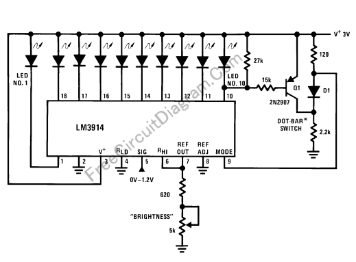
This LED (Light Emitiing Diode) display consist of 10 LEDs to indicate the level of an input signal. If the signal is small, only LED#1 will light, and if the signal level getting higher then you’ll se the light dot will move through LED #2, #3, #4, … and so on. When the signal input drive the dot until LED […]

Read more
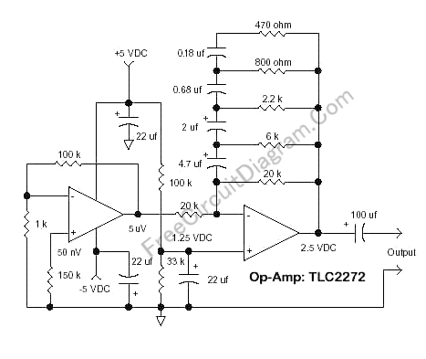
Pink (Flicker) Noise Generator

The circuit’s schematic diagram shown in the figure below is a flicker noise generator, an implementation of flicker noise analog modeling presented in NBS technical note #604, “Efficient Numerical and Analog Modeling of Flicker Noise Processes” by J.A. Barnes and Stephen Jarvis, Jr. With the component values shown the schematic diagram,  the circuit will give a 1/f noise slope from […]

Read more

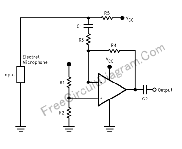
Balanced Input Microphone Pre-Amplifier, High Quality Audio For Long Distance Wiring

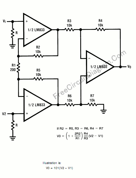
Balanced input has three connections, ground, positive signal, and negative signal. When we trace the signal using oscilloscope, if we take the ground as the reference, then the negative signal and the positive signal has similar shape but with inverted polarity. If we measure the signal between positive and negative output, the we have two times larger signal than what […]

Read more

Baxandall Tone Control Using LM833: The Circuit’s Schematic Diagram and The Formula

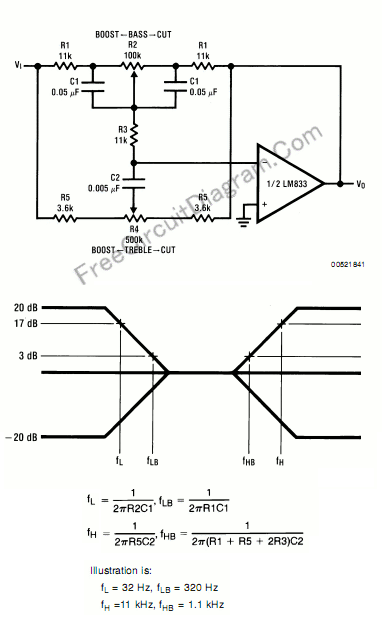
This circuit is similar to our previous tone control circuit, a bass-treble tone control circuit, but here we present the formula for design your tone control’s custom frequency response. Here is the schematic diagram and formula of the tone control circuit: Almost all op-amp type can be used, as long as they have high input impedance, much higher than the […]

Read more

Butterworth Second Order High-Pass Filter: The Circuit and The Formula

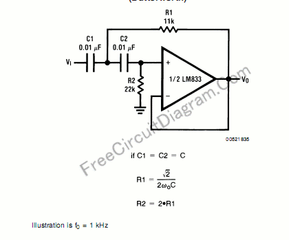
For high pass filter, this circuit is similar to low-pass filter circuit, but the position for resistors and capacitor are interchanged. Here is the circuit’s schematic and formula: Similar with low pass design guide, the resistor and capacitor should be chosen according to the formula, and the resistor value should be: Much higher than equivalent leakage resistance of the capacitor. […]

Read more

20 Watts Car Stereo Amplifier Using TDA2004

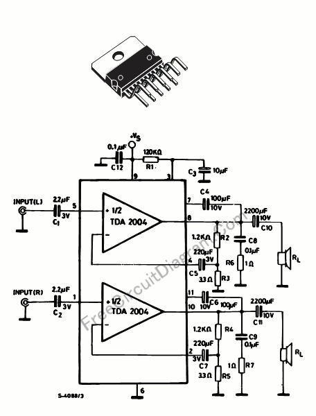
The main features of this powerful MULTIWATT®  package (a trademark of SGS-THOMSON Microelectronics), a  power amplifier IC chips designed specifically for car radio application, are the high current capability (3.5A) and the capability to drive a very low impedance (down to 1.6R). Here is the schematic diagram of the standard circuit as shown in its data sheet. TDA2004 has low  […]

Read more
1 16 17 18 19 20 21