Sealed Lead Acid Battery Charger: Dual Step Current Charger Mode

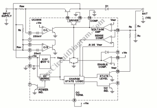
All of the necessary circuitry to optimally control the charge and hold cycle for sealed lead acid battery can be implemented using UC2906 series of battery charger controllers. These integrated circuits monitor and control both the output voltage and current of the charger through three separate charge states; a high current bulk-charge state, a controlled over-charge, and a precision float-charge, or standby state.

This lead acid battery charger uses dual step current charging scheme. The dual step current charger is useful when a large string of series cells must be charged. To guarantee equal charge distribution between the cells, the holding-charge state maintains a slightly elevated voltage across the batteries with the holding current, 1H. The difference of dual step current charger from float charger is that at the bulk-charge state, is that when V12 is reached, no over-charge state occurs since Pin 8 is tied high at all times. Regulating the holding current is done by mean of current sense amplifier. In some applications, a series resistor, or external buffering transistor, may be required at the current sense output to prevent excessive power dissipation on the UC2906. For more information about this sealed lead acid battery charger circuit design, please refer to the UC3906 application info here. [Circuit schematic diagram source: Unitrode Products Application Information]