Overvoltage Protector with Relay
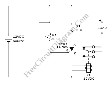
An overvoltage protector circuit is shown in the schematic diagram below. This circuit will work to disconnect the protected device from the power supply when an overvoltage occurs at the supply. This circuit uses a silicon-controlled rectifier (SCR) and normally-closed 12-V relay, K1. The silicon-controlled rectifier is connected in parallel to 12-V line to monitor for the overvoltage condition. This applied signal is sensed by the SCR’s gate. Here is the schematic diagram of the circuit:
The K1’s contacts remain closed and SCR1 remains off as long as the applied voltage stays below a preset value. When overvoltage occurs, the SCR1 will be triggered causing K1’s contacts open and halt current flow to the load. R1 is used to set the trigger point of SCR1.