Main Power-Battery Backup Switcher
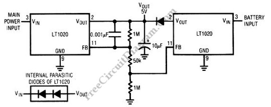
For critical operation, the power loss can be unacceptable. It might be costly if a financial data is lost from the memory in the middle of point of sale transaction, or even it can be deadly if some life support devices fails during critical surgery. The schematic diagram presented here is a battery backup regulator circuit, useful for memory or […]
Read more