Adjustable 0-30V Power Supply

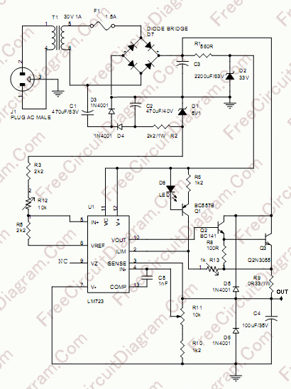
The first thing you must have in your workshop/lab is power supply. In experimenting many new electronic circuit design, it is easier if you have a flexible adjustable power supply. Here is an adjustable 0-30 volts power supply design. The circuit schematic diagram is shown below.
The core of the circuit is 723 voltage regulator integrated circuit. A Darlington pair Q2 Q3 boost the current to give 1A output. The minimum voltage adjustment for this regulator IC is 2 volts above V-. Zero volt is achieved by supplying the V- with a voltage under -2V, so the output can be adjusted to zero. The negative supply is provided by the components around D3 and D4, stabilized by 5.1 Zener diode.
The variable resistor R3 is used to set the current limiter, so your power supply will be save even when you short its output to ground. To set the zero point, turn the R11 potentiometer to minimum (counter clockwise) and adjust the R12 trimmer potentiometer until the output is zero. After this setting, turning the R11 potentiometer to the maximum will give around 30V output. If at the maximum position the output is smaller than 30V, it’s likely caused by the components tolerance, you can lower the R10 value. Make sure you use larger track for ground connection on the PCB, and provide sufficient heat sink for Q3.
Finally, here is the parts list:
[TABLE=4]