Autoranging Circuit

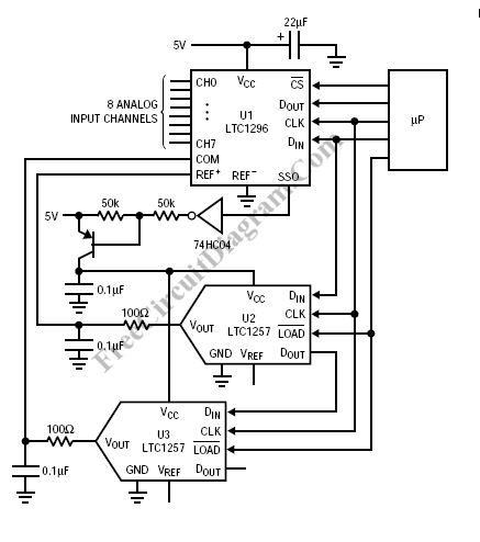
Autoranging is useful to extend the measurement range of an available ADC (analog-to-digital converter). Autoranging will best implemented for multiplexed input. LTC1257 is appropriate for system autoranging, adjusting an ADC’s full-scale range.

During the conversion process, U2 and U3 receive the full and zero scale codes, respectively, that correspond to a selected multiplexer channel. For example, let channel 2’s span begin at 2V and end at 4.5V. When a host processor wants a conversion of channel 2’s input signal, it first sends code that sets the output of U2 to 2V and U3 to 4.5V, fixing the span to 2.5V. The processor then sends data to the LTC1296 selecting channel 2. The processor next clocks the LTC1296 and reads the data generated during the conversion of the 3.5VP-P signal applied to channel 2. As other multiplexer channels are selected the DAC outputs are changed to match their spans.
Fixed reference voltages lead to a problem because it is common to have input signals with different zero scale and full-scale magnitude requirements. Matching the reference voltage span to each multiplexer input is the chosen method to solve the problem: although the ranges selected for some of the inputs may take advantage of the full range of ADC output codes, inputs that do not span the same range will not generate all codes, reducing the ADC’s effective resolution. [Circuit’s schematic diagram source: Linear Technology Application Notes]