Programmable Pressure Transducer Circuit

Silicon pezoresitive-bridge pressure transducer (SPPT) is very popular in medical, industrial, environmental, and automotive pressure sensor application. The general architecture of SPPT uses a thin micromachined silicon diaphragm incorporates a implanted piezoresitive Wheatson-bridge strain-gauge.
The transducer design allows only a small diaphragm deflection sin it has limited elasticity, and this produces only a very small output signal, only about 1% modulation of the bridge resistance elements. This small signal off course need a high gain, low-noise, and temperature-stable DC amplification. The signal conditioning circuit must also include stable, high resolution, preferably noninteractive, zero and span trims.
Another complication of SPPT application is the large temperature dependence of both total bridge resistance and peizosensitivity (the ratio of bridge output to excitation voltage times pressure). Bridge resistance increases with temperature while peizosensitivity decreases. Some SPPT designs (e.g. the Lucas NPC-410 series) carefully equalize these opposite-sign tempcos. The payoff comes when such SPPTs are excited with constant current because the increase with temperature of bridge resistance (and therefore of bridge excitation voltage) then cancels the simultaneous decrease of peizosensitivity.
Ordinarily, a ~10mV/psi pressure-proportional strain gauge signal is output differentially on pins 2 and 4 of the sensor, superimposed on the ~50 times larger bridge excitation voltage. The standard method for separating the bridge’s differential pressure signal from the common mode bias voltage would be to use an expensive, high performance differential amplifier.

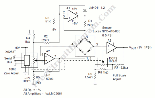
In the Figure, the A2 circuit provides for the precision adjustment, via DCP1, of any transducer initial null offset error. To accomplish this, the bridge excitation voltage is programmably attenuated by the R2, R3, R4, R5 network and applied to DCP1. The range for the zero adjustment voltage is from +22mV to –22mV. The resolution is 172uV and is proportional to the bridge excitation voltage, thus improving the temperature stability of the zero adjustment. Boosting the ~10mV/psi bridge signal by 100x to a convenient 1V/psi output level is the job of the A3 noninverting amplifier via its feedback and calibration network consisting of R7 through R9 and DCP2. The gain of A3 can be varied from 75 to 125 with a resolution of 0.2. Bridge bias is provided by the A1 circuit which uses voltage reference D1 and current sense resistor R1 to generate a constant-current bridge drive of I = 1.225V / 2kOhm = 612uA. The net result of the combination of transducer and the Figure 4 circuitry is a signal conditioned precision pressure sensor that is compatible (thanks to DCP1 and 2) with full automation of the calibration process, is very low in total power draw (< 1 milliampere, most of which goes to transducer excitation), and (equally important) is low in cost. [Source: Intersil Application Notes]