Pulse Width Modulator Using 555 IC

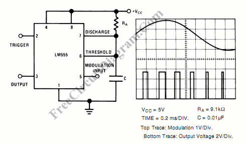
Pulse width modulator produce a PWM signal, a pulse with a constant frequency but with the duty cycle vary according to a modulating signal. Here is the schematic diagram of pulse width modulator circuit using 555 IC as the active component:

This pulse width modulator circuit need external pulse train input to trigger the the 555 monostable circuit. This trigger input sould be a square wave signal with a fixed frequency. The output of this pulse width modulator circuit will have same frequency with the trigger input, but with its pulse width proportional to the modulating input signal at pin 5. [Circuit’s schematic diagram source: National Semiconductor Application Notes]