IR-Linked Temperature Sensor

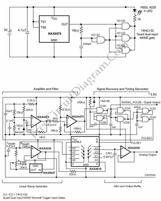
This is a circuit that transmits temperature data over an IR link and it allows the isolation of temperature sensor. It is a good solution of obtaining temperature readings from points at potentials a few tens of volts from ground by linking a temperature probe only by an IR connection to the readout point. This circuit consist of a temperature sensor, an IR receiver, and an IR transmitter. Here is the circuit:

As the temperature sensor, this circuit uses the MAX6576 that will convert temperature into period. This sensor is connected to the IR transmitter. The IR transmitter is triggered to generate a short (about 10µs), high-intensity IR pulse by each positive-going transition of the square-wave output from the MAX8576. This circuit also uses a 74HC132, the three fourth gates are paralleled and used as the IR LED driver and the remaining one gate is used as a positive edge differentiator. This circuit powered by a CR3032 lithium battery.
The second circuit is a IR Receiver/Signal Processor that is used to receive the IR light pulses generated by the temperature sensor. It will transform the IR light pulses into two types of output: analog and digital. The analog output is a DC voltage proportional to the IR signal period and the digital output is simply a standard logic pulse recovered from the IR signal. This circuit consist of four circuit blocks : the signal-recovery/timing generator, the linear ramp generator, the buffered sample-and-hold and the amplifier/filter. [Source: maxim-ic.com]