High Precision Voltage-Controlled Oscillator (VCO)

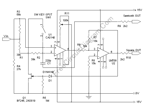
This voltage-controlled oscillator circuit is very compact and has a good linearity. The author said that the precision could be better than 0.01% If this circuit is properly constructed. Moreover, this circuit gives three different output waveforms: square, triangle, and sawtooth. This three waveform is important for music synthesizer and measurement devices. Here is the circuit’s schematic diagram:
The oscillator consist of a mixer (U1) and a comparator with hysteresis U2. if U2 has positive output (+15V) then FET Q1 will be conducting, and if the output is negative then the FET will be open, in other words, the FET will function as an electronic switch. The voltage at pin 2 U1 will be kept constant at 1/3 Vin (set by R3 R4) by op-amp feedback mechanism. If Q1 is switched off then the capacitor C1 will be charged from Vin to U1 out through R1 and R2. The effect of this charging is that the voltage seen at U1 (pin 6) output will increase. After this pin 6 U1 voltage reach the upper threshold of U2 Schmidt trigger (the hysteresis is set by R6 R7), the U2 output will swing to V+ and switch on the Q1 switch. After Q1 switched on, the capacitor C1 current now reverse it’s direction, discharging, and the U1 output will be decreasing. After reaching the lower threshold level of U2 Schmidt trigger then U2 output will swing to V-, switch the Q1 off and the restart the cycle.
The sawtooth output will be a triangle wave with same frequency as the square wave output when SW1 is open. If SW1 is closed then the C1 capacitor discharging will be very fast and the triangle output will change into sawtooth waveform with two times higher frequency. The amplitude of sawtooth or triangle output will be about (+ -) 8.3V, and the square output will be (+ -) 15 V. Except for R5, R9, and R10 those require no high precision, all resistors should be 1% tolerance or better.
The output frequency will follow the equation:
f =(Vin . R6)/(180.R7.R2.C1),
where the frequency is in Hz, capacitance in Farad, and resistance in Ohm. Vin is the control voltage in Volt. With the values shown in the schematic diagram, the voltage-frequency conversion rate will be 357Hz/Volt. Setting the R11 potentiometer is done by shorting the negative and positive inputs of U1 to ground and adjust R11 to give zero volt reading at U1 output (pin 6). [circuit ‘s schematic diagram source: elector]