10-Band Graphic Equalizer Using Gyrator Circuit

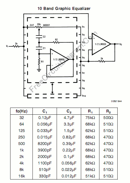
Graphic equalizer is a filter which it’s overal frequency response can be adjusted easily by sliding the potentiometer knob, and the potentiometer’s knob positions will naturally mimic the frequency response of the filter, and this is very user friendly. Many methods have been developed by electronic engineers to make audio equalizer, such as Baxandall’s type and Gyrators emulation type. Here we present the gyrator emulation type. Look at the circuit’s schematic diagram below.
The schematic diagram shows two op-amps circuit. The first op-amp (left) emulate a high-Q LC network using RC and active (amplifier) circuit, called a gyrator circuit, actually pass the signal from signal line to ground (do an attenuation on the frequency band). The second op-amp is configured as a non-inverting amplifier. Look at this amplifier, both non-inverting and inverting input is actually connected to the signal line via a potentiometer. Without the LC emulator (the gyrator) connected to the potentiometer tap, the signal that reach the inverting and the non inverting will eliminate each other and give a flat response (no boost or cut), and it’s about same when the gyrator is connected at the center position of the tap. When the tap position is close to the signal source at 3k resistor (far from negative input), the signal (for a certain frequency band) after the resistor will be shorted to ground by the gyrator, and now that frequency range of the signal that reach the positive input will be cut. When the gyrator tap position is slided close to the inverting input, then the signal at positive input is not shorted to ground anymore, and the negative feedback that attenuate the op-amp gain (for the selected frequency band) will be shorted to ground and the gain for that frequency band get higher (boost). [Circuit’s schematic diagram source: National Semiconductor’s Application Notes]