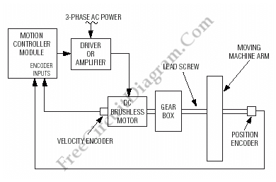
Motion (Motor) Control Servo System Block Diagram

Below is a block diagram of a modern automated systems incorporate closed-loop feedback for motion control. They typically include a servo system that consist of feedback elements and motor driver combined in a manner. This will give accurate and stable control over speed and position. Below is the illustration of the various system-level components of a typical servo system.
For processing the high-speed encoder signals, typical motion-controller cards and modules include a motion-control IC, a microprocessor, and a DSP or custom ASIC. Velocity and direction of rotation signals to the driver or amplifier is provided by the controller which in turn provides the proper levels of voltage and current (power) to operate the motor. We must have address the following items at the system level to design robust and fault-tolerant motion-control system with feedback during design: Controller-encoder input circuits (receiver circuits), Receiver circuit PC-board layout and Encoder-signal cabling system. Motion-controller inputs, such as hard-wired emergency stop and limit inputs, should also be considered when designing a fault-tolerant feedback system though not addressed in this article. [Servo system block diagram source: maxim-ic.com]