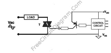
SCR And Triac Triggering Circuit With A Positive Power Supply

The control-circuit output current has to be amplified when the gate current required to trigger the device is higher than the control-circuit output current capability. For example, A lot of MCUs feature output pins with a current capability around 30 mA today. With IGT, they can switch Triacs safely up to 15 to 20 mA. Below are two solution if a Triac with a 35 or 50 mA IGT has to be controlled by such an MCU. First, Use several MCU output pins in parallel (the best is to use a separate gate resistor between each output pin and the Triac gate to ensure a good current repartition between each pin). And second, use a bipolar transistor shown in the schematic diagram below.

With the bipolar solution, the only way is use a PNP transistor to keep the current sourced to the gate. To set its drive reference to a stable bias, a PNP transistor has to be used, which is the power supply (Vdd) in this case.
This is another drawback of the positive power supply topology. A PNP transistor has to be used instead of an NPN transistor to amplify the control circuit output current. Than an NPN, a PNP transistor has a lower current gain and higher price. [Circuit’s schematic diagram source: STMicroelectronics]