Variable Q Twin-T Notch Filter

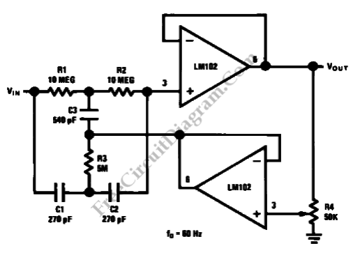
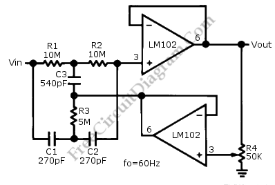
This is a Variable Q Twin-T Notch Filter circuit. This circuit is used when low Q is needed. The Lower Q gives some advantages in rejecting the signal where the signal deviate slightly from the null of the notch network. The Q of this circuit can be adjusted from 0.3 to 50. This circuit has two voltage follower. The second voltage follower gives the signal feedback from the fraction of the output to the C3 and R3. The feedback signal affect the notch Q. This circuit uses potentiometer to vary the Q. Here is the schematic diagram of the circuit:
If the C3 is increased by 1-10 percent, the depth of the notch will decrease and the value of Q will increase. The network will become a tuned amplifier and provide voltage gain when C3 is increased by 10-20 percent. The voltage gain of this circuit is 400. The circuit will osillate and give sine wave output when the C3 is raised greater than 20 percent.
This circuit is very simple and easy to use. Polycarbonate or silver mica capacitor should be used with precision to reduce the notch frequency shift with temperature. The component match affect the depth of the notch. To reduce the trimming required for 60dB notch, 1 percent capacitors and 1 percent resistor can be used. This circuit has to be featured with the bypassing section that use 0.1uF disc capacitors as close as possible to power supply pins to improve the stability of the op-amp. [Circuit’s schematic diagram source: National Semiconductor Application Note]
