F/V Converter for Frequency Difference Measurement
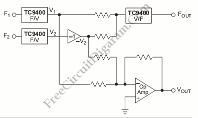
This is a Frequency Difference Measurement circuit. This circuit consist of two TC9400 that is configured in the F/V mode. So, the TC9400 will convert both frequencies into proportional analog voltage(V1 and V2). This circuit also uses unity gain inverter to invert V2. After that, this circuit will add the V1 and -V2 using the summing op-amp. That operation will give a voltage proportional to the frequency difference between F1 and F2. Here is the circuit:
After get the proportional voltage then the voltage will be converted to frequency by TC9400 V/F. It will produce the frequency output proportional to the difference between F1 and F2 because the input of TC9400 V/F is the summing junction to an op-amp. [Circuit’s schematic diagram source: Microchip Application Note]