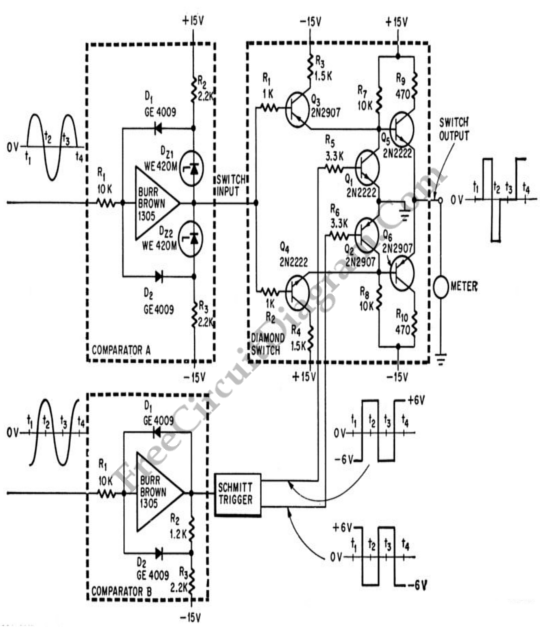
Phase-Shift Meter for Audio Frequency Signal

Simple phase shift measurement can be done by squaring both the measured and the reference, then compute the difference of the two signals. The accuracy of the circuit shown in the schematic diagram below is 1% UP to 2000 cps.

This circuit is used in computers and for high speed analog instrumentation. Negative value for zero phase shift is indicated by the zero center DC ammeter, zero for 90′ phase shift and some maximum value for 180′ phase shift. [Circuit’s schematic diagram source: seekic.com]