Inductance Meter Circuit

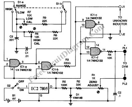
This inductance meter is actually an adapter to your digital voltmeter (DVM). Using this circuit now your voltmeter is capable of measuring inductor value. Inductance meter is very helpful in designing switch mode power supply, since its often needed to wind the coil by hand and measure the inductance fro trial and error to get the required value. Here is the schematic diagram of the inductance meter adapter circuit:

This circuit is designed to provide twi measurement range. The low range will measure inductors with inductance value between 3uH to 500uH, and the high range will measure inductance values between 100uH and 5mH. To calibrate this inductance meter adapter, connect a digital voltmeter, swith the voltmeter to 200 mV range, short the test probe and adjust the zero (R1) to give zero millivolt reading on your digital voltmeter. To calibrate the low range of this inductance meter adapter, switch the voltmeter to low range position, and select 2 V range for the digital voltmeter. Test a known inductor that has value around 400uH, adjust the low calibration pot to give correct reading of 1mV / uH. If you use a 400uH inductor then you must adjust the calibration to give exactly a 400mV reading. For high range calibration, switch the range selector to high position and use a known inductor around 5 mH, adjust the high calibration pot to give 100mV per mH. A 5 mH inductor should give a 500mV reading on your DVM. [Source: Marc Spiwak]