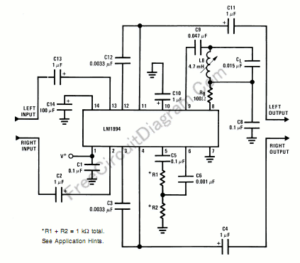
LM1894: Single Chip Dynamic Noise Reduction System (DNR)

The LM1894 is a stereo noise reduction circuit suitable for audio playback application. The DNR system is non-complementary, meaning that it does not require encoded source signal. The system is compatible with almost all prerecorded tapes and FM broadcasts. This noise reduction system uses psycho-acoustic masking and an adaptive bandwidth filtering to achieve 10 dB noise reduction. This DNR would save circuit board space and cost because it use only a single integrated circuit chip with few additional components.
The DNR system should always be placed before tone and volume controls. Placing DNR system after tone or volume control won’t work because any adjustment of these controls would alter the noise floor seen by the DNR control path.
The sensitivity resistors R1 and R2 may need to be switched with the input selector, depending on the noise floors of different sources, i.e., tape, FM, phono. To determine the value of R1 and R2 in a tape system for instance; apply tape noise (no program material) and adjust the ratio of R1 and R2 to open slightly the bandwidth of the main signal path. This can easily be done by viewing the capacitor voltage of pin 10 with an oscilloscope. Adjust the values of R1 and R2 (their sum is always 1 k) to slightly deflect the scope trace. The small deflection seen on the scope does not indicate signal level, but rather instantaneous bandwidth of the two filters; it should not be interpreted as a signal-level. To ease the setting of this bandwidth sensitivity, a 1k potentiometer can be used to replace R1 and R2. To change the minimum and maximum value of bandwidth, the integrating capacitors, C3 and C12, can be scaled up or down. because the bandwidth is inversely proportional to the capacitance, changing this 0.0039 µF capacitor to 0.0033 µF will change the typical bandwidth from 965 Hz–34 kHz to 1.1 kHz–40 kHz. With C3 and C12 set at 0.0033 µF, the maximum bandwidth is typically 34 kHz. The DNR system should be switched from maximum bandwidth to nominal bandwidth with tape noise as a signal source.
Bypassing the DNR system can be done using a double pole double throw switch. The capacitor on pin 10 in conjunction with internal resistors determine the attack and decay times. The attack time can be adjusted by selecting the size of C10. Decay times can be decreased by paralleling a resistor with C10, and increased by increasing the value of C10.
Finally, the components L8 (4.7mH), R8 (100R), C8 (0.1uF), and CL (0.015uF) form a 19kHz FM pilot tone filter, and these components can be omitted if the input never come from FM receiver, and the only component left is C9 connected directly across pin 8 and pin 9. [Circuit’s schematic diagram source: National Semiconductor’s Application Note]