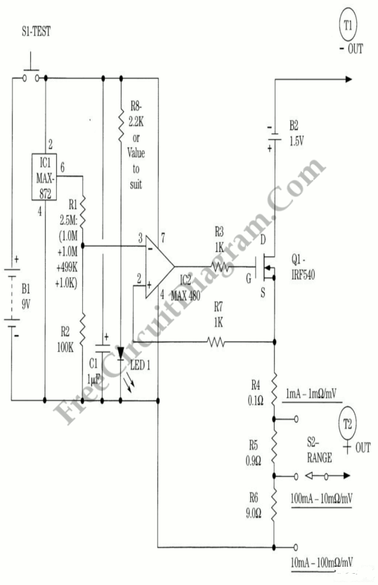
10 mA, 100 mA, and 1 A Current Source

The circuit of the milliohm adapter is shown on the following figure. Under test, it can apply 1 A, 100 mA, or 10 mA to the resistance. If your voltmeter is set on the 2 V range, the current application will indicate the resistance directly in millivolts. B1 is the high current source. B1 is an alkaline battery capable of generating the 1 A used in the circuit’s highest-current application mode. This must be an alkaline battery. A three position switch enables user selection of the desired applied current to the DUT. S1 performs as a dual function on/off switch. Pressing S1 turns on the circuit when a measurement is to be made, which consist of a micropower voltage reference chip IC1 and an op amp, IC2. The output of 101 is 2500 V and that voltage is divided by R1 and R2, producing 0.1 V at the current source along with Q1, the 1,5 V battery and the DUT’s resistance. That’s applied to the DUT through the two output terminals, T1 and T2. You can directly read the resistance of the DUT when you connect your voltmeter across these terminal. It is advisable for reasons of economy not to keep S1 depressed for protracted periods on that range because the 1 A range of the instrument will drain the 1.5 V alkaline battery faster than the 9-V battery, or else the battery life will suffer. We can halt the current source through Q1 and the associated circuit path by releasing S1, and thus will shut off the current flow from the 1.5 volt battery. If you disconnect the test leads, the same effect will occur.
