Powerline Carrier System Transmitter for Audio (Music/Speech)


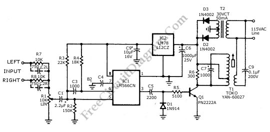
Power line carrier system is common in home appliances networking. One benefit of using this kind of transmission line is that we don’t have to deal with additional wiring for data or signal communication, since all we need is already provided when we plug the power jack into the power outlet/stop contact. The circuit depicted in the schematic diagram below is suitable for high-quality transmission of music or speech. This circuit has some advantages like wireless FM transmitter/receiver operates over standard power lines, noise free and high quality. The total harmonics distortion (THD) of this circuit is under 1/2% with frequency response of 20-20, 000 Hz. This circuit also used for mono transmission to single remote speaker, so two input terminals are provided. This circuit can transmit the carrier with distance that include all outlets in and around a suburban home and yard.
The circuit is built from several functional blocks: power supply, audio pulse modulator, and high frequency pulse injector. The power supply block is built around T2, D2, D3, C6, IC2 and C9. This power supply provides 12V regulated power for audio-pulse modulator block around IC 1, and provide 15V (unregulated) to the high frequency pulse injector around T1. The audio signal coming from left and right channel will be mixed at the potentiometer, and will modulate the frequency of the square wave (pulse) signal generated by the VCO (voltage controlled oscillator) chip IC1. This modulated pulse is then employed to drive the T1 transistor, which drive the transformer T1 to inject the pulse into the power-line. The capacitor C3 should be 1 nF to produce carrier frequency about 170kHz, and the signal distributed in the power-line could be picked up by the similar transformer (T1) with capacitor coupling C9.