Small AM Transmitter Circuit: Using Logic Gates!

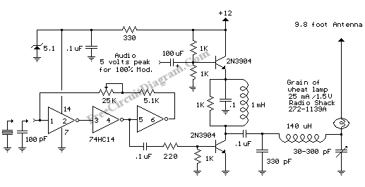
For you who has failed to build radio transmitters, this circuit worth a try. This circuit uses 74HC14 hex Schmidt trigger as the oscillator, and you can choose to use capacitor for low cost goal or quartz crystal for better stability. For quartz crystal, you can choose any frequency between 00.7-1.6MHz, but around 1.6MHz is recommended since it need shorter antenna for good radiation (although still far smaller than 1/4 wavelength).
Using a capacitor, you can replace the quartz crystal with a 100pF cap, and now the frequency can be adjusted using the 25k variable resistor (connected in series with 5.1k resistor). The Schmidt trigger 74HC14 generate a square ware signal, and then amplified by the first transistor configured as a class C RF amplifier. The second transistor (the upper one) is worked as the modulator, to variate the amplitude of the RF signal in accordance with the audio signal level that need to be transmitted.
With no modulation, the voltage at output will be about 6V (half of the supply voltage), and the current at the antenna will about 20mA if properly tuned. Tuning the antenna is done by 140uH inductor and 30-300pF variable capacitor. The 140uH inductor can be made using a 2 inch length of 7/8 inch (OD) PVC pipe wound with 120 turns of #28 copper wire. A small ‘grain of wheat’ lamp is used to indicate antenna current and optimum settings. Because the antenna will be much smaller than 1/4 wavelength, tdepending on the antena size, the radiated power at 20 milliamps can be around 14 micro watts. [Circuit ‘s schematic diagram source: Bill Bowden’s circuits collection]