Another RF Field Strength Meter

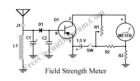
This circuit is another radio frequency (rf) field strength meter, similar with our previous field strength meter circuit, but with lower supply voltage (only a single cell 1.5V battery). Here is the schematic diagram of this rf strength meter circuit:

To use, turn on transmitter and meter; adjust C1 for peak reading. Turn off transmitter and adjust R1 for a perfect zero reading on the meter. Turn on transmitter (with no audio modulation) and go to your monitor point(s) and take readings. Your monitor point(s) should be many meters/yards away from your antenna, but obviously must be where the signal is still strong enough to register on your instrument. After taking a set of readings, you can experiment with your antenna or transmitter system, then take another set of readings and determine whether your signal strength was increased or diminished. Keep your readings in your engineering logbook. Make note of whether it’s been dry or rainy in recent days; moist soil might give slightly better propagation.
The parts list:
- Q1: 2N107 or GE-2, etc. (This is a pretty old circuit design. Any equivalent PNP transistor should work.)
- R1: 50K potentiometer
- R2: 1K, 1/2 watt
- R3: 1K, 1/2 watt
- J1: jack for antenna; the antenna must be insulated from the case
- D1: 1N34
- meter: milliammeter, 0 to 1 mA range
- antenna: a 30 to 50 centimeter piece of stiff wire, or a generic telescoping antenna
- L1 and C1 are chosen so that they form a resonant tank circuit at the frequency of interest.
[Circuit’s schematic diagram source: Meddium Wave Alliance]