Simple PWM Circuit Using Inverter Gates

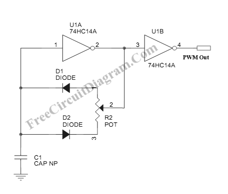
This PWM circuit needs only two inverter gates, so you can build up to 3 independent PWM circuit using only one IC chip, since there are at keast 6 inverter gates in one IC package. Here is the schematic diagram of the circuit:

Please remember that you should connect any input pins of any unused gates to ground or to Vcc in order to stabilize their output to a determined value, preventing them of swinging to high or low if the input pins are floating and axposed to noise. If you use only two gates (only one PWM circuit) as shown in the figure, then you should connect the pins 5, 9, 11, 13 to ground (or to Vcc). You can change the value of the C1 and R2 to change the frequency of the PWM. Select R2 (the potentiometer) of any value between 10k and 100k, then you can vary the C1 to find the apppropriate frequency. This circuit can be used to control a DC motors, heaters, or incandescent lamps.