UHF Antenna Booster

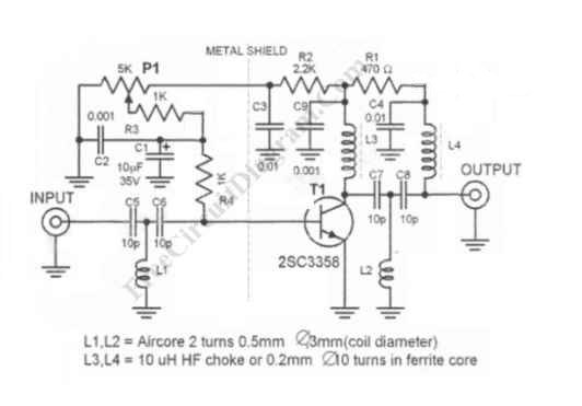
UHF antenna booster can be used for better reception, especially when you’re far from TV station / relay transmitter. This UHF antenna booster works in 400-850 MHz range. Here is the circuit diagram of the UHF antenna booster:

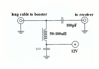
The circuit use only one transistor, but it gives you 10 to 15 dB amplification, enough for many situation. The most important part is that the transistor circuitry should be shielded from the input circuitry, as shown in the schematic diagram by the dashed line. This ircuit is powered via the signal cable, since the antenna booster circuit must be wired as close as possible to the antenna. This is very important since the amplifier should amplify the signal acquired by the antenna, not the noise picked by the cable from the antenna to the circuit. The antenna and the booster circuit can be installed above your house’s roof. Long 75 ohm coaxial cable can be drawn from the this booster circuit output to the power supply unit close to TV set.

Just insert a 50-10o uH inductor or RF choke between the output cable and the power supply. Tap the output signal from the output cable using a small 100pF ceramic capacitor to block the DC voltage from the power supply. Adjust P1 to get the best reception, and this should set the working current consumption to around 5-15 mA.