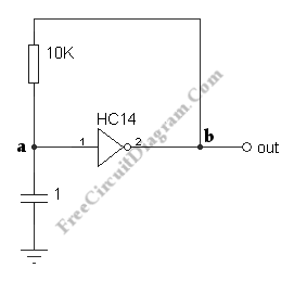
Single Gate Relaxation Oscillator

Below is a relaxation oscillator circuit using a 74HC14, an inverter with a Schmitt trigger input. It’s mean that the transition point for an increasing input is higher in voltage than the transition point for a decreasing input. The difference is called the “hysteresis.” Such an input is very useful for a slowly-varying inout or one with noise. The opposite transition will not occur immediately since once a transition is made. Because of that, the input will not “bounce” or chatter. To make this circuit work, such an input is required and the transition levels will be displayed on the oscilloscope. The capacitor voltage oscillates between the lower and upper transition levels, which for the HC14 are typically 2.0 and 3.0 V and cary with the supply voltage.

An oscillator must be hand-adjusted to produce a certain frequency since these value may vary considerably between different chips. The duty cycle is not exactly 50%. Take a look at the waveform then you will understand what is going on. Because the inputs load the RC circuit too heavily, this circuit will not work with a 74LS14. Take a note a little “ringing” at the top of the rising transition of the output.