Single Supply Precise Full Wave Rectifier Using CA3140 Op-Amp

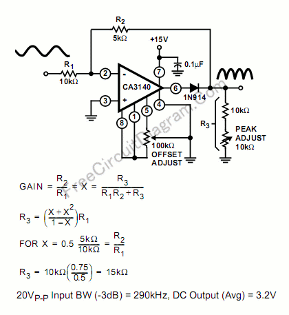
The schematic diagram below describe a precise full-wave rectifier circuit. The circuit needs only a single supply, make it suitable for battery operated devices.
During the positive cycle of the input, the signal is directly fed through the feedback network to the output, give the transfer function of Vout=R3/(R1+R2+R3). At the positive cycle of the input, the diode 1N914 disconnect the op-amp output because the op-amp output is zeroed.
During a negative cycle of the input signal, the CA3140 functions as a normal inverting amplifier with a gain equal to -R2/R1. When the equality of the two equations shown in the Figure is satisfied, the full wave output is symmetrical. Note that the output is not buffered, so the output should be connected only to high impedance stage, with impedance much higher than R3. Errata: the figure shows an equation of GAIN=(R2/R1)=X=(R3/(R1R2+R3)) that is wrong, and the right formula should be GAIN=(R2/R1)=X=(R3/(R1+R2+R3)). [Circuit’s schematic diagram source: Intersil Application Notes]