VHF-UHF Antenna Amplifier (Booster) 40-500MHz
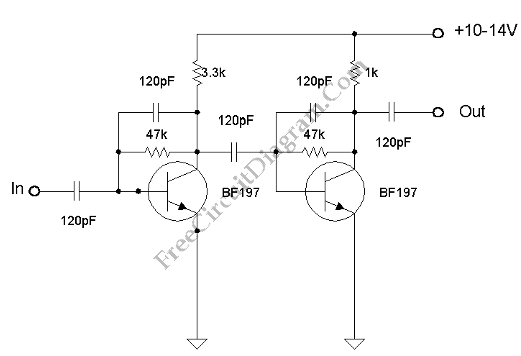
This amplifier has VHF (very high frequency) and UHF (ultra high frequency) response, you can use it for receiver booster for example. Here is the schematic diagram of the circuit: The current consumption is very low, under 20 mA for 14V voltage supply.  Lower current consumption can be achieved if we use 10V power supply, the current consumption would be […]

Read more
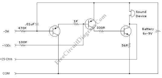
Multilevel Continuity Tester

This continuity tester not only show if a connection is continue or not, but also determine the range  of  its conductivity level. Here is the schematic diagram of the circuit: Finding wiring trouble is easier if we know the quality of the connection, and this continuity tester give rough estimation. Small transistors will be sufficient for this circuits since the […]

Read more

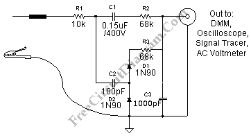
Automatic AF-RF Probe

Using this automatic probe, you can see measure both audio signal  (AF) and radio signal (RF). If audio signal is being measured, the path of the signal is via C1. Audio signal can’t pass the C2 since the capacitance is very small and having very high impedance for audio frequency signal. If you measure high frequency (radio frequency, RF), now […]

Read more

Differentiator Operator with Op-Amp

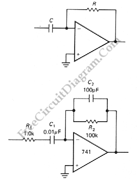
Another application of OP-AMP is differentiator. Differentiator circuit produce an output if the input is changing. The output can positive or negative, depends on the change of the input: whether it’s decreasing or increasing.  This circuit is a bias stable. The current is produced by the rate of change of input voltage because the inverting input is grounded. Here is […]

Read more

Summing Amplifier with Op-Amp

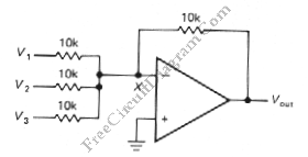
One of inverting amplifier application is for summing several electric signals. The output of this circuit produce the sums of the input voltages.  We can use both positive or negative voltage for the inputs. The input resistors doesn’t have to be  same values. The input can be expanded to several digits. Since the point X is a virtual ground, the […]

Read more

Differential Amplifier with Op-Amp

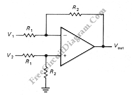
The schematic diagram below shows a differential amplifier circuit. This circuit is used to get a common-mode rejection ratios. This circuit need a precise resistor matching to get common-mode rejection ratios because the current source uses matched resistor ratios. Here is the circuit: The gain of this circuit is determined by following equation: gain=R2/R1 The Vout is determined by following […]

Read more

Ultrasonic Security Circuit – Video Tutorial

This is a video tutorial of ultrasonic security. This tutorial explains how ultrasonic security circuit works. The ultrasonic security circuit consist of two main circuit. First is a transmitter circuit which transmit the ultrasonic signal. And then a receiver circuit, it is used to receive signal from the transmitter. The front of receiver circuit is a signal receptor and the […]

Read more
1 20 21 22 23 24 54