High Frequency Colpitts Crystal Oscillator
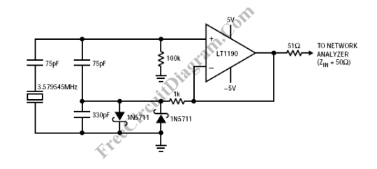
Op-amps has been widely used in low frequency oscillator (frequency <= 100kHz), but we can actually use it for high frequency crystal oscillator as long as we have an op-amp with the proper bandwidth. An excellent gain stages can be implemented using LT1190 and LT1191 op-amps. Here is the schematic diagram of the circuit: Two Schottky diodes is employed to […]

Read more
Video Line Driver

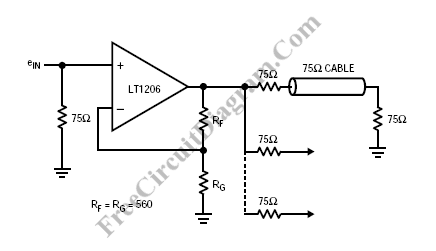
LT1206 is suitable for driving multiple video cables since it has 60MHz bandwidth, 250mA output current capability, and low output impedance. Please keep in mind about unterminated line effect when driving multiple cables. A reflected wave would propagate back to the driver an cause a crosstalk to other lines since the driver output is non zero impedance. The schematic diagram  […]

Read more

Colpitts Crystal Oscillator

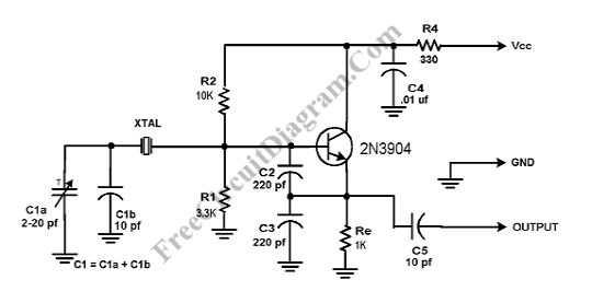
Crystal Colpitts oscillator can be implemented using a transistor and a parallel mode crystal. Here is the schematic diagram of  the circuit: In this circuit, the crystal acts as an inductance. A large value capacitive divider is used between gate, source, and ground, and a small series capacitor is placed in the crystal circuit. You should choose the components values […]

Read more

Video Switch

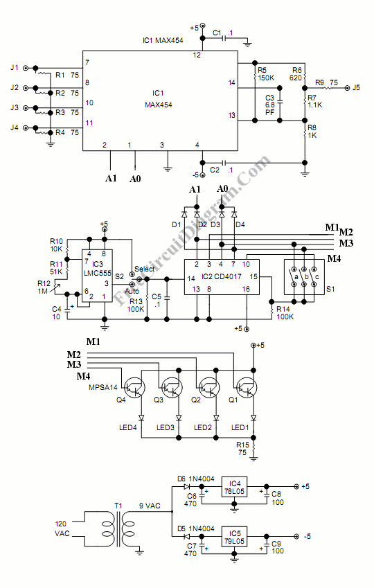
As the price of security camera going down, installing the camera in the shop, office, or even in home becomes economically feasible. Providing a dedicated monitor for every installed camera is not efficient, and your CRT monitor might suffer phosphor  burn if it used to display static image from only one camera.  To display 1, 2, 3, or 4 cameras […]

Read more

Video Wire: Enable Video Transmission Via Long Cables

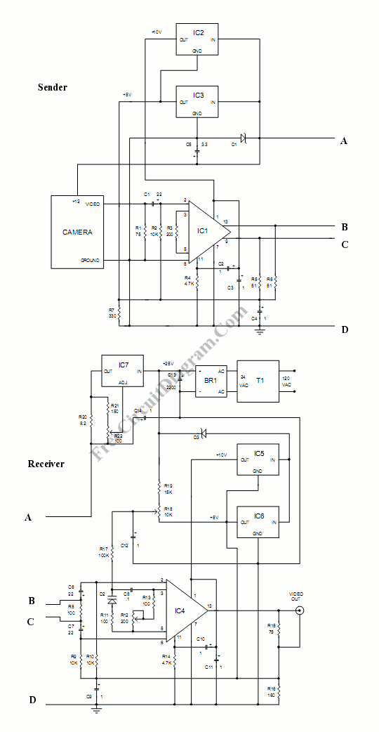
This circuit enables you to connect your camera with very long wire. The circuit is actually a video amplifiers. At the sender part, the amplifier is used to make a stronger signal. This stronger video signal then can be transmitted through the long cables. The signal is transmitted using balanced mode, where two wires are driven in the opposite phase. […]

Read more

UHF Antenna Booster

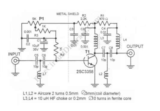
UHF antenna booster can be used for better reception, especially when you’re far from TV station / relay transmitter. This UHF antenna booster works in 400-850 MHz range. Here is the circuit diagram of the UHF antenna booster: The circuit use only one transistor, but it gives you 10 to 15 dB amplification, enough for many situation. The most important […]

Read more
1 6 7 8 9 10