LM1893 Powerline Modem
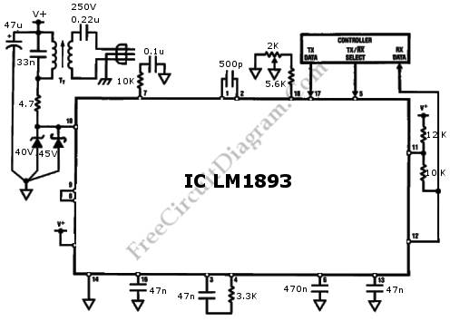
This schematic diagram shows an LM1893 powerline modem circuit. This circuit is used to transfer information between remote location by using the power mains. This circuit uses LM1893 that is used as a power line interface for half-duplex (bi-directional) communication of serial bit stream of virtually any coding. Here is the schematic diagram of the circuit : To give maximum […]

Read more
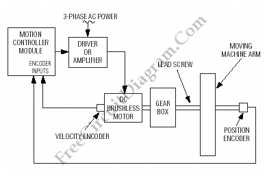
Motion (Motor) Control Servo System Block Diagram

Below is a block diagram of a modern automated systems incorporate closed-loop feedback for motion control. They typically include a servo system that consist of feedback elements and motor driver combined in a manner. This will give accurate and stable control over speed and position. Below is the illustration of the various system-level components of a typical servo system. For […]

Read more

Discrete Bass Booster Circuit

This bass booster circuit can be used filter the input signal as part of internal circuit of an active subwoofer circuit. This circuit is not only boost the bass (low) frequency, but also attenuate high frequency as well. You might consider this circuit as low pass filter, since the high frequency response is not flat, not really as expected in […]

Read more

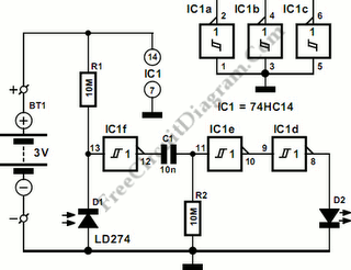
74HC11 Infra-Red Remote Control Tester

This is Infra-Red Remote Control Tester circuit. This circuit is used to test go/no-go of any remote control transmitting infra-red (IR) light. The supply of this circuit is 3V battery. This circuit has some advantages, such as fits in a compact enclosure, built from inexpensive parts and a handful of commonly available. As a quasi-analogue amplifier, this circuit uses Schmitt […]

Read more

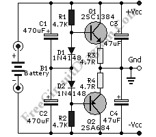
Discrete Active Virtual Ground

You might find op-amp based active virtual ground, but here a  schematic diagram shows that you can build such circuit using discrete components.  This circuit uses most any complementary pair of small-signal transistors such as PN2222A and PN2907A. The diode that is used in this circuit is generic small-signal types like 1N914. You can also use other transistor type as […]

Read more

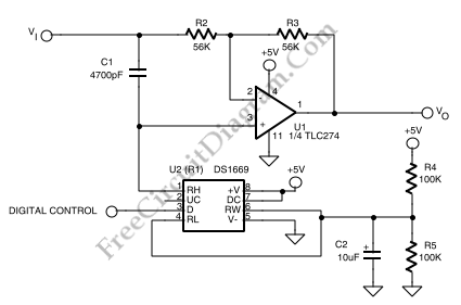
Digitally Controlled Phase Shifter

As shown in a schematic diagram below, this circuit implementation of phase shifter circuit  is well suited to using digital potentiometer  to control the resistive control element of  the phase shifter. The phase at a given frequency is now under control of a digital signal using this circuit which is optimized for phase-shifting over the audio range. By using a […]

Read more

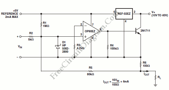
OP90 4 mA to 20 mA Current Loop Transmitter

An output of 4 mA to 20 mA that is linearly proportional to the input voltage is provided by the current transmitter on figure below. Line rejection is 0.0005%/volt and linearity of the transmitter exceeds 0.004%. Here is the schematic diagram of this current loop circuit: The REF-02EZ provides biasing for the current transmitter. The output current is regulated by […]

Read more
1 2 3 4