Low Noise Microphone Pre-Amp with Op-Amp
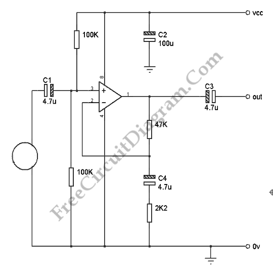
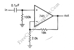
Microphone pre-amp is a very simple circuit, most all low noise op-amp will be sufficient for this circuit (TL071, TL082, OPA371, NE5534, etc). This circuit will be suitable for dynamic microphone, electret microphone (or a condenser microphone with active circuit inside). A condenser microphone (without voltage bias source) won’t work for this circuit. If you want to use it, you […]

Read more
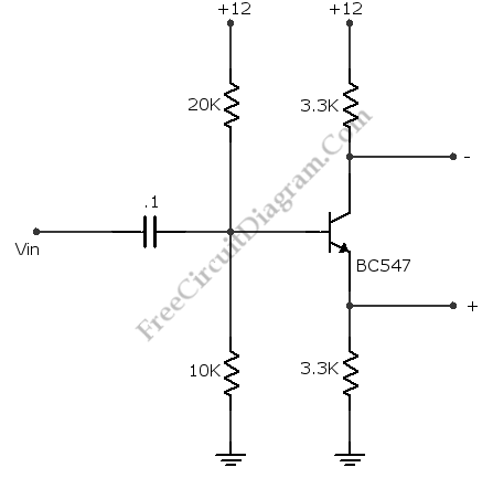
Complement Phase Inverter with Single Transistor

This is a complement phase inverter circuit. Sometimes this circuit called a paraphase amplifier circuit. This circuit has two output signals that is have sufficient “headroom” because this circuit is biased. The transistor will be saturated when the collector decreases, the emitter voltage increases and set the limit. Here is the circuit: This circuit can produces a peak to peak […]

Read more

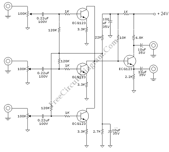
Discrete (Transistors) Audio Mixer

This audio mixer is built with transistors. This audio mixer circuit is unique, not based on low input impedance amplifier. Most of audio mixer circuit is based on low impedance amplifier, so a high resistance signal source point can be summed together without disturbing each other. This mixer circuit is different, since the circuit is based on something like open […]

Read more

VHF-UHF Antenna Amplifier (Booster) 40-500MHz

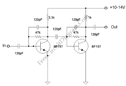
This amplifier has VHF (very high frequency) and UHF (ultra high frequency) response, you can use it for receiver booster for example. Here is the schematic diagram of the circuit: The current consumption is very low, under 20 mA for 14V voltage supply.  Lower current consumption can be achieved if we use 10V power supply, the current consumption would be […]

Read more

Differential Amplifier with Op-Amp

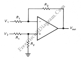
The schematic diagram below shows a differential amplifier circuit. This circuit is used to get a common-mode rejection ratios. This circuit need a precise resistor matching to get common-mode rejection ratios because the current source uses matched resistor ratios. Here is the circuit: The gain of this circuit is determined by following equation: gain=R2/R1 The Vout is determined by following […]

Read more

Photovoltaic (Solar Cell) Current To Voltage Converter

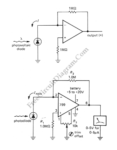
The simplest I to V converter is the humble resistor. However, presenting a nonzero impedance to the source of input current is the disadvantage of the humble resistor. If the device providing the input current has very little compliance or does not produce a constant current as the output voltages changes, this can be fatal. A photovoltaic cell is a […]

Read more
1 2 3 4 5 7