High Precision Voltage-to-Frequency Converter (VFC) Using CA3130 Op-Amps

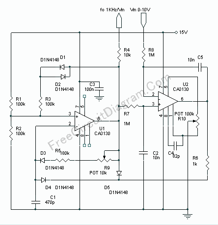
Voltage to frequency is very useful in many situation, such as transmitting temperature measurement using standard voice radio transceiver. This circuit (see the circuit’s schematic diagram) uses only two CA3130 op-amps, but the performance is good enough. The linearity of the voltage-frequency transfer is better than 0.5% and the temperature coefficient is lower than 0.01% !!
Assume that the output voltage of U1 is 15V, C1 will be charged with time constant (R9+R5)C1, flowing through R9, R5, D3, and C1. This charging will continue until the voltage of pin 2 (U1) get higher than the non-inverting input voltage at pin 3. After this, the output voltage of U1 will drop to zero (ground) and the non-inverting input pin 3 will drop to about 5V, set by the R3 for hysteresis. Now C1 will discharge its current through D4 and R6, at a rate determined by the voltage level at U2 output. If the C1 voltage has decreased below 5 volt then the U1 output will swing to 15V and the cycle will be restarted. At U1 positive input, the voltage level is the average of the pulse output of U1. The output of U1 is a positive pulse with constant width, and the space is variable depends on the discharging rate of C1 which is depend on U2 output. If the voltage level of this positive input of U2 is smaller than the control voltage at the negative input then the output of U2 will decreased toward negative supply (ground), therefore the discharging rate of C1 will be increased and the pulse output of the U1 will have shorter space, thus increase the voltage level at C3 until the it’s equal to the control voltage level at negative input of U2. If the voltage level at positive input is higher than the negative input, then the output of U2 will increase toward positive supply (15V) giving a reversed action to keep the level of negative and the positive input equal.
Because D3 and D4 are needed to separate the charging and discharging control of C1, and the diodes have different characteristics at different temperature, D1, D2, and R3 are provided to introduce similar reference voltage variation of positive input as seen in the negative voltage variation caused by D3 and D4 at different temperatures. Use R10 pot to correct the offset error of U2 and R9 to fine tune the voltage-to-frequency conversion rate to exactly 1kHz/Volt. [Schematic Source: RCA Application Note]