Variable (Adjustable) Current Limiter Circuit

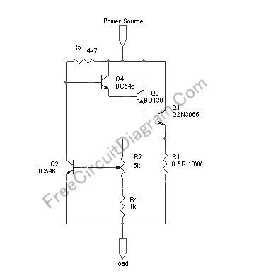
This circuit provide automatic current limiting up to 8.4A. Unlike current limiter that uses only a resistor, this current limiting circuit doesn’t drop the voltage, or at least keep the voltage drop at minimum, until a certain current amount is exceeded. This current amount limit is adjustable from 1.4 A to 8.4A using a potentiometer. You can modify the component value to give different current limiting range. Here is the circuit’s schematic diagram:
The resistor R1 is there to sense the current. At R2 potentiometer at minimum resistance (the center tap connected to R1), if the current drawn by the load reach 1.2A then the voltage across R1 reach 0.6V and Q2 begin conducting, thus shorting the base voltage of Q4 to ground. This shorting action reduce the base current and therefore reduce the output voltage sensed by the load, and prevent the current to flow further. If you need the current limiter to limit at lower threshold range, you can change the R1 to 1R and you’ll get about 0.7A to 4.2A adjustment range.
Because of the power dissipation capability of 2N3055 transistor, at the worst case that the load is shorted to ground (zero resistance), if you limit the current to 8.4 A then the circuit can handle maximum source voltage of 14V, while limiting the current at 4.2A can handle up to 27V source voltage. The maximum voltage can be handled by this circuit is 60 volt, but at that maximum voltage you can only safely set the current limit at 1.9A in the extreme condition, when the load is shorted to ground. Please make sure the Q1 transistor has sufficient heat sink. [Circuit Schematic Source: Designed by FreeCircuitDiagram.Com]
Update (some questions from our reader)
I have some questions regarding this circuit:
- How is the input ground and the output ground connected in this circuit? I’m guessing that the ground is connected from the load to he power source, but that would not be true if this is intended to be a two input/ two output device.
- If my load is equivalent to 1.7 ohms, and my input is 8.4 V, the current through the current limiter should be about 5 A. If I limit the current to the load from 5A to 2A, what is happening the 3A directed away from the load? Is it being dissipated as heat or what?
- Will this circuit provide continuous current at or below the set current limit threshold? In this example I am dropping 5A to 2A. Will the circuit continue to provide 2A, or will it shut off current like an open switch?
[Name is kept private]
- The ground is not shown in the schematic, and the ground of the power source and the load should be connected as a common ground for this circuit to work.
- Because of triple transistor Q1-Q3-Q4 biasing, there will always be about 1.7V voltage drop between power source and the junction of Q1 emitter and R1, when the current limiting is not triggered (below the threshold), let’s call this voltage drop VD1. This voltage drop (VD1) will be getting higher when the current limiter is triggered. Another voltage drop is introduced at R1, let’s call it VD2, adding more voltage drop which is proportional to the drawn current (no matter the limiter is triggered or not). In the questioned case, let’s assume that the voltage source is increased (about 12.6V) so that the voltage at the load is 8.4V (load current 5A). At this condition, when the current limit is set above 5A then there would be a certain value of VD1 (about 1.7V) and VD2 (2.5V). When the current limit is then set to 2A then the limiter is triggered and the transistors will regulate the VD1 to produce a fix current of 2A at load. Now the power dissipation of the transistor will be getting higher since it produces more VD1 drop, and the power dissipated by load and R1 will be getting lower.
- The circuit will produce a continuous current, 2A in that case.