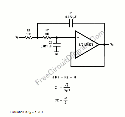
A second order filters can be constructed using LC (inductor-capacitor) passive circuits, and they have been implemented for radio frequency for cheap and simplicity. For audio frequency range, unfortunately the size for the inductor and capacitor become too large, space consuming, and the most important is they’re really expensive. Because of this, active filter is commonly used for audio application. Here is the circuit’s schematic diagram:
You can use the formula to modify the component values to suit your need. Please keep in mind that the resistor value should be:
- Much higher than the operational-amplifier’s (op-amp’s) input impedance.
- Much higher than equivalent leakage resistance of the capacitor.
- Doesn’t draw excessive current-violating the maximum allowed op-amp’s output current.
Generally, for higher capacitor value, it’s leakage current would be higher and you must use lower resistors to get the formula works as expected. [Circuit's schematic source: National Semiconductor's LM833 Application Notes]
Possibly Related Articles:
- Butterworth Second Order High-Pass Filter: The Circuit and The Formula
For high pass filter, this circuit is similar to low-pass filter circuit, but the position for resistors and capacitor are interchanged. Here is the circuit’s schematic and formula: Similar with... - First Order Low-Pass Active Filter: The Circuit Schematic Diagram and The Design Formula
The simple low-pass filter is shown in Figure below. The filter has a 20dB/decade roll-off after its corner frequency fc. Its low-pass frequency gain (f->0) is defined by R3/R1. This... - Voltage-Controlled Low-Pass Filter with LM13600 OTA
Below is a circuit that demonstrates one use of an OTA using an LM13600. Take a note that the strange symbol stand for OTA. In this circuit, negative feedback is... - Differential Low-Pass Filter and The Design Formula
Multiple Feedback (MFB) is the best filter topology to use for differential low pass filters. Here’s the circuit diagram: To design this filter, a corner frequency is chosen based on... - Low Pass Filter with Enhanced Step Response
Effect on the system’s time-domain response is a common problem when designing lowpass filters. The system may fail to recognize significant changes in time because pushing the cuttoff frequency lower... - 1st-order-3-Way Crossover Circuit Design Using Free Online Tool
Designing passive crossover network for your speaker system is easy, just like what shown in our previous crossover design article, but now we can design many types of crossover even... - Sallen and Key Lowpass Filter
This a Sallen and Key Lowpass Filter circuit. This circuit is a second-order active filter. This circuit can be changed to highpass filter by interchanging capacitors and resistors. This circuit... - Twin-T Notch Filter
This is a Twin-T Notch Filter circuit. This circuit is a filter that can remove a certain frequency band. This is a passive filter that uses two filters in parallel,... - Transistor Hum Notch Filter
The function of this circuit is similar with the hum filter in our previous circuit, but it use transistors instead of op-amps. It uses BC109 transistors, but any low noise... - Variable Q Twin-T Notch Filter
This is a Variable Q Twin-T Notch Filter circuit. This circuit is used when low Q is needed. The Lower Q gives some advantages in rejecting the signal where the... - Bootstrapped Twin-T Notch Filter Produces High Q
This is a Bootstrapped Twin-T Notch Filter circuit. This circuit can generate high Q by combining the twin “T” with LM102 voltage follower. The generated Q is greater than 50.... - Hum Filter, An Ultimate Weapon To Remove AC Line Noise
You might think that hum noise is produced by electronic device with improper design, yes you’re right. And you might choose to solve the trouble maker, the source. You begin...

| 

