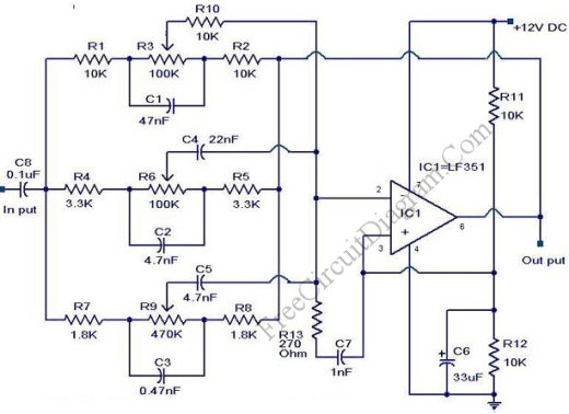
Unlike the 10-band graphic equalizer in our previous circuit that use a gyrator circuit, this 3-band graphic equalizer circuit uses Baxandall topology, similar with the Baxandall tone control but with additional mid frequency control. The figure below shows the schematic diagram of the circuit.

The operational amplifier employ an LF351 IC chip, but any low noise op-amp will be suitable for this equalizer application. Unlike in the application of  10 channel equalizer, the passive components  in this 3-bands graphic equalizer circuit are not critical since this circuit doesn’t need a critical frequency band separation.  Resistors with 5% tolerance are more than enough, and ceramic capacitors with 10% tolerance will be adequate. Off course you can use better component but the performance improvement won’t be noticeable. This circuit need only a single supply, so this would be great for car audio or simple home audio application. [Circuit's schematic diagram source: circuitstoday.com]


Possibly Related Articles:

  • 10-Band Graphic Equalizer Using Gyrator Circuit
    Graphic equalizer is a filter which it's overal frequency response can be adjusted easily by sliding the potentiometer knob, and the potentiometer's knob positions will naturally mimic the frequency response...
  • 5-Band Graphic Equalizer Circuit Using LA3600 Integrated Circuit Chip
    Using a special purpose single IC chip LA3600, we can build a graphic equalizer with low components count.  The internal design of the chip uses transistors gyrator circuit, with connections...
  • Electronic Fuse for DC Circuit
    Tired replacing your power supply fuses, or it cost too much because too often to blow? Use this electronic fuse and your life would be easier. It is good for...
  • Radio Modem Circuit
    This radio modem is popular for amateur radio packet application. This radio modem is powered by the data and control lines, so it need no additional power supply. Just plug...
  • Sample and Hold Circuit Using CA3140 Op-Amp
    The schematic diagram below shows a very simple sample-and-hold circuit using the CA3140 as the readout amplifier for the memory capacitor. The CA3080A is used as both input buffer amplifier...