Sawtooth Wave Oscillator Using 555 IC

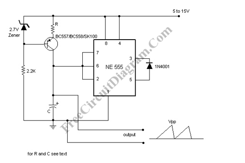
Sawtooth wave oscillator circuit can be implemented using several methods, here we present one design that employs 555 IC. Here is the schematic diagram of the circuit:

The core of the circuit uses general 555 oscillator configuration, but instead of using a fixed resistor to limit the current for charging the capacitor, we use a constant current source. This change the voltage ramp profile of the capacitor from logarithmic to linear. The diode is connected from pin 5 to the output (pin 3), This force the capacitor to discharge almost to it’s ground level, not only from 2/3 to 1/3 VCC as the standard configuration. The current source depends on the resistor R value, and the current will be [[zener diode voltage ] – [base-emitter voltage of the transistor] /R]. You can vary the resitor or the capacitor value to change the frequency of this sawtooth oscillator. Please note that you must keep the charging current low since it will be shorted to gorund everytime the discharging cycle take place. [Circuit’s schematic diagram source: electronic-circuits-diagrams.com]