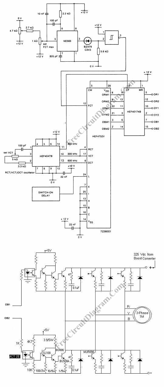
Controlling the speed of three phase ac motor is done by controlling the frequency of the power line supply,  since the motor is synchronized with the line frequency. Three phase ac motor speed controller is actually nothing more than three phase sine wave power inverter with variable frequency. The three phase power inverter is a complex circuit, but fortunately there is an integrated circuit chip for this purpose. Here is the schematic diagram of the controller circuit:

ac motor controller circuit schematic

For the final motor driver circuit, you can see the component values are shown only for OB2 channel, but the others are similar. This 3 phase ac motor controller use optical isolation, so you must be careful in designing the layout, to make a clear separation between low and high voltage network. This separation is useful for minimizing the risk of hazardouz electrical shock.


Possibly Related Articles:

  • Enabling 3 Phase Motor to Operates with Single Phase Supply
    Capacitor have been use for decades to operate 3-phase motors on single-phase power. Two single-phase wires are connected to two of the inputs on a 3 phase motor on this...
  • 2 Phase and 3 Phase Motor Drivers
    The schematic diagram below show 2-phase and 3-phase motor driver circuits. This circuit can used to drive an AC motor because this circuit has an integrated power operational amplifier, built-in...
  • Single Phase Induction Motor Control Theory
    The most used is single-phase induction motors. This motors operate with a single phase power supply, only have one stator winding and are also squirrel cage. The motor is not...
  • Small DC Motor Speed Controller
    Electric motor has been widely used as motion control, and many  type of motor controllers  have been designed to provide variable speed drives for the motor. The best controller is...
  • LM378 24 V DC Proportional Motor Speed Control
    National LM378 amplifier is used as a basis for economical proportional motor speed controller. This integrated circuit is able to deliver 700 mA continuous current for such DC motor applications...
  • Bi-Directional Motor Drive with Speed Control
    This is a circuit of Bi-Directional Motor Drive with Speed Control. This circuit is designed to replace the conventional drivers. The component cost can be reduced and efficiency will increase...
  • Series-Wound Direction And Speed Motor Control
    This is a motor controller circuit that  control the speed  and direction of series-wound Motors. This circuit employs silicon controlled rectifiers (SCR) Q1-Q4, that are triggered in diagonal pairs. The...
  • Mixer or Sewing Machine Motor Speed Control
    It will be effective to use simple half wave motor speed control with small universal  ac/dc motors. Two amps RMS is the maximum current capability. The control gives excellent torque...
  • Simple Proportional-Integral Motor Speed Control
    Another example of frequency-to-voltage  converter application similar with RPM/Speed Indication is motor speed control. Here the converter is used to measure the actual speed which will be fed back to...
  • Motor-Speed Control Employs Class-D Power Amplifier
    A dual benefit for battery-powered portable devices is provided by Class D audio amplifier. The produce much less power dissipation than do their linear cousins and they enhance battery life....
  • Synchronized TRIAC for Small Induction Motor Speed Control
    We can use this circuit diagram to adjust the speed of a low-power induction motor, such as those which can be found in fan application. The function of capacitors C1,...
  • DC Motor Speed Control – Video Tutorial
    This is a video tutorial of DC motor control. This video shows how to control the DC motor speed. In this video, speed of the DC motor is controlled by...