Gamma Correction Circuit
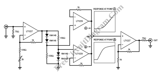
Transducers is used in video system to convert optical signal to electrical signal in the acquisition. In the display, transducer is used to convert electrical signal back to light. Transducers often have a transfer function (the ratio of signal in to light out) that is unacceptably nonlinear.
The newer technology of video camera transducers (the improved versions of vidicon-like tubes and CCDs) are adequately linear, however, picture monitor CRTs are not. The following equation shows the transfer functions of most CRTs follow a power law:
Light Out = k • VSIG?
where gamma (?) is the exponent of the power law (gamma ranges from 2.0 to 2.4) and k is a constant of proportionality. This deviation from nonlinearity is usually called just gamma and is reported as the exponent of the power law. Gamma value of 1 results in a linear transfer function. The typical CRT will have a transfer function with a gamma from about 2.0 to 2.4. Such values of gamma give a nonlinear response which compresses the blacks and stretches the whites. Cameras usually contain a circuit to correct this nonlinearity. Such a circuit is a gamma corrector or simply a gamma circuit. [Circuit’s schematic diagram source: Linear Technology Application Notes]