Programmable Levels High Speed Pulse Generator

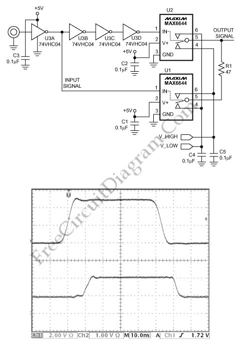
This is a Programmable Levels High Speed Pulse Generator circuit. This circuit consist of Lilliputian dimensions associated with the sub-micron geometries of many analog and most digital processes also advanced CMOS logic gates or analog comparators. Here is the circuit :

The advanced CMOS logic gates or analog comparators is used to create faster digital edges. The sub-micron of digital processes is used to accelerate rise/fall times and turn-on/ turn-off times of analog switches. A SPDT switch will not short the two switched terminals together during a transition because it guaranteed by the a feature of the analog switch that hinders its use as a pulse generator is the intrinsic built-in delay.
A SPDT analog switch (U1) configured as the pull-up/pull-down driver controlled by the input clock signal (ø1). To create a delayed clock signal (ø2), ø1 is sent through a high-speed CMOS inverter (U3). A SPDT analog switch (U2) configured as the output driver driven by the delayed clock.
The steady state condition is obtained when the ø2 is high and ø1 is low. The presence of a low-impedance pull up (R1) is closely followed by the closing of U2 and provides drive for the signal transition. This circuit requires 5V logic input signal, and produces output between 1V to 2V. [Source: maxim-ic]