ESR Meter (Equivalent Series Resistance Meter)

The ESR (Equivalent Series Resistance) of an electrolytic capacitor is normally just a low voltage capacitor (such as a 1000uF, 16V cap), small fraction of an Ohm for a high capacitance, and can be as high as two or three Ohm for a low capacitance, high voltage cap (1uF,450V). This resistance increases when the capacitor ages, and it often does do such a dramatic way that the equipment completely ceases to function or even blows up semiconductors. To find capacitors that have degraded to 100 times their normal resistance while their capacitance remains fine is very common.
An additional beauty of an ESR meter is the capacitor can be checked in almost all cases while they are in circuit. This is so because a good capacitor would measure like a short circuit, so while measurement, any other parts connected in parallel will have minimal influence. This features are the reason why an ESR meter is irreplaceable tool for troubleshooting electronic equipment.
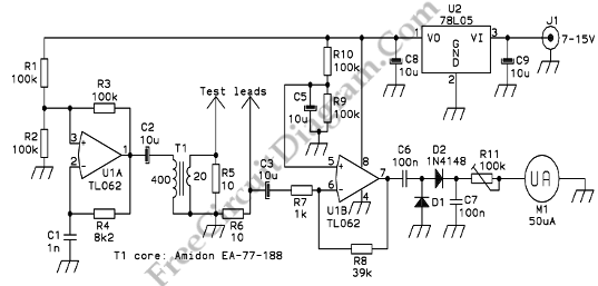
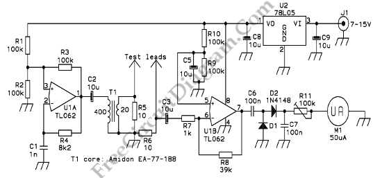
The circuit below works by applying a 50kHz, 200mV square wave to the capacitor under test, in series with a 10 Ohm resistor. The AC voltage occurring across that resistor is measured and displayed on a meter. So the whole thing is just a simple ohmmeter that uses ultrasonic AC for measurement instead of usual DC used by every common ohmmeter. It does not make semiconductor junctions enter conduction, which further helps to make this meter suitable for checking capacitors mounted in a circuit since the AC voltage used is so slow.
The transformer is the only part that could pose problems to inexperienced builders. This transformer is made using an Amidon ferrite core, type EA-77-188, which is a tiny double-E core having a cross section of 22mm2, and external dimensions of about 19x16x5mm total. The nylon bobbin that Amidon delivers with it is used, wound a primary winding consisting of 400 turns of AWG #36 wire. As secondary, 20 turns of AWG #26 wire is wounded. You can adjust the turn numbers in inverse proportion to the cross section area if you have a larger or smaller core. The wire size is not important, the gauges I used are about 3 or 4 numbers thicker than necessary, while at the same time this bobbin has room for wire at least two numbers thicker than the ones used. Thus, for each winding, you can choose from about 6 different wire gauges with negligible impact on the performance.
Adjust its set screw for accurate zero position using the galvanometer’s original scale. Short the test leads together with the circuit powered up, and adjust R11 precisely for a full-scale reading. Now, take the meter front cover off, get a pencil and a few resistors in the range of 1 to 22 Ohm or so. Mark the corresponding deflections on the meter scale using the resistors as test objects. You keep this crude hand-drawn scale indefinitely, or you use it as a template to draw a definitive scale on the computer, print it and install it in the meter is depend on your choice. [Source: Homo Ludens Electronicus]
