ADP1821 Step Down DC-to-DC Converter

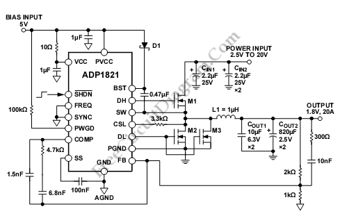
This is a ADP1821 Step Down DC-to-DC Converter circuit. This circuit uses ADP1821 that is synchronous pulse-width-modulated (PWM), step-down controller, inexpensive and versatile. It can drive all N-channel power stage to regulate an output voltage as low as 0.6 V. The output voltages that can be provided by this circuit is from 0.6 V to 85% of the input voltage. To handle large MOSFETs for point-of-load regulators, the ADP1821 is sized. Here is the circuit:

The ADP1821 is used in many applications like processor core power in telecommunications, high performance servers, DSP, medical imaging and industrial applications. The input voltage of ADP1821 is from 1.0 V to 24 V and operates from a 3.7 V to 5.5 V.
Using ADP1821 has soma advantages such as it has selectable-pin that is used to select the fixed frequency of either 600kHz or 300kHz, and it minimize the external component size and cost. If the ADP1821 is used in noise sensitive applications, it can be synchronized to an external clock. The synchronization gives switching frequencies between 300 kHz and 1.2 MHz. To limit the inrush current from the input supply during startup, as a unique adjustable lossless current-limit scheme utilizing external MOSFET sensing and reverse current protection during soft start for precharged outputs, the ADP1821 is equipped with soft start protection.
The ADP1821 is available in a 16-lead QSOP and operates over the –40°C to +125°C junction temperature range. [Circuit’s schematic diagram source: analog.com]