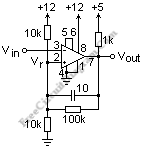
LM311 Comparator with Hysteresis

An LM311 comparator circuit with the pin numbers is shown in the schematic diagram figure below. The ground for this transistor is at pin 1 and the open collector output is at pin 7. It is shown pulled up to the logic voltage of +5 with a 1k resistor, which is typical. The LM311 output can sink 8 mA. A comparator’s output is essentially binary, high or low. Pin 8 is V+ and pin 4 is V-. The total supply voltage can go up to 36V. V- can simply be connected to ground as here if the comparator threshold is above ground by a volt or so.

The supply voltage to the LM311 does not have to be the same as the logic supply. If not use as a balance adjustment (like the nulling of an op-amp), pin 5 and 6 should be shorted together. Pin 3 is the inverting input and pin 2 is the noninverting input. It is usual to establish the reference voltage Vr at pin 2 by a voltage divider, as shown. The reference voltage (threshold) is about 6 V. Positive feedback is provided by the 100k resistor from the output to pin 2. The threshold is reduced a little when the output goes low, and the threshold is raised a little when it goes high. They furnish a “snap” action to the comparator because these changes are opposite in direction to the change in the voltage at pin 3 that produced them. The fractional change in the threshold is roughly the value of the divider resistors in parallel divided by the feedback resistor, here 5/100 or 0.05. This gives a difference of 0.25 V with a 5V supply, called the hysteresis. The threshold for the output to go high to low is 0.25 V higher than the threshold to return from low to high. To give a little extra punch to the hysteresis, there is a small speedup capacitor of 10 pF across the feedback resistor. The change will be rapid and definite with these provisions. Test the circuit, and note how it operates. When low, the output can light an LED, saving one DMM. Check out other circuit collection and their explanation at http://mysite.du.edu/~etuttle/electron/elecindx.htm.