230VAC Temperature Fan Control

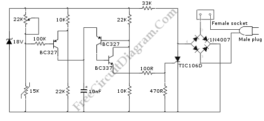
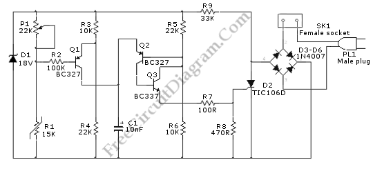
This is a 230VAC Temperature Fan Control circuit. This circuit is used for 230Vac operation. The R9 can be changed to 15K 2W, if the AC operation is 115V. This circuit uses the principle of Wheatstone bridge. The Wheatstone bridge is made from R3-R4 and R1-P1. P1-R1 produce a temperature-sensitive “variable” voltage and a fixed two-thirds-supply “reference” voltage is produced by R3-R4. This circuit uses BC327 transistor as a bridge balance detector. This circuit must be calibrated before used by adjusting the potentiometer until the “reference” and “variable” voltages are equal at a temperature. At this condition, the Q1 is cut off because the voltage of emitter and the base is same. Here is the schematic diagram of the circuit:
If the temperature is higher than “balance”, the C1 will be charged since the Q1 becomes forward biased. This circuit is supplied by a 100Hz half-wave voltage. This supply is produced by means of D3-D6 diode bridge without a smoothing capacitor. The Zener diode is used to fix the supply to 18V. The supply of this circuit is not completely DC but rather trapezoidal shape. The triggering device is made by the Q3 and Q2, that produce a short pulse suitable to drive the SCR. C1 is used to generate a variable phase-delay pulse-train related to temperature. The switching RFI is minimal because the variable phase-delay pulse-train is synchronized with the mains supply “zero voltage” point of each half cycle.