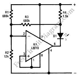
A battery level indicator circuit is depicted in the schematic diagram below. This circuit is designed for 9V battery operation, as this circuit will start dimming below 7V and will be completely turned off at 6V. If you want the LED indicator not to dimming but just abruptly turns off at below 6V, then you can remove R3, and change R1 to 330k.

[Circuit's schematic diagram source: National Semiconductor Application Note]
Possibly Related Articles:
- LM10 Battery Voltage Threshold Indicator
A battery threshold indicator circuit shown in the schematic diagram below has current regulation mechanism in driving the LED. A sufficient current should be satisfied at the minimum voltage but... - LED Audio Level (VU) Indicator and Alarm: The Dot Turns to Bar When The Signal Reach The Maximum Level!
This LED (Light Emitiing Diode) display consist of 10 LEDs to indicate the level of an input signal. If the signal is small, only LED#1 will light, and if the... - Water Level Indicator with Alarm
This is a Water Level Indicator with alarm circuit. This circuit is used to indicate the amount of water present in the overhead tank. Not only that, but this circuit... - Two Transistors Lead Acid Battery Monitor
Three separated LEDs is used on this battery monitor circuit. For red LED, it’s turn on from 6v to below 11v and turns off above 11v. For the orange LED,... - LM1830 Single Chip Water Level Sensor Circuit: Basically A Conductive Liquid Level Sensor
For any electrically conductive liquid level measurement, this single chip circuit is very compact and simple. This circuit is an ac excited fluid level sensor, which uses alternating current to... - Single Transistor Lead Acid Battery Monitor
We can make a very simple battery monitor using a dual-colour LED and a few additional components. When the red and green LEDs are illuminated, the LED produces orange. The... - Ni-Cad Battery Zapper, A Rechargeable Battery Reconditioner
Ni-Cad (NiCd, NiCad) battery, sometimes doesn’t work as expected, gives no power and cannot be recharged. In this situation, the battery need to be reconditioned. It’ is possible that the... - Current Loop Light Level Detector
This circuit is two wire light level detector, we don’t separate wires for power this sensor system and for delivering the output signal. With current loop, we do both function... - Single Cell Battery Meter Amplifier
A meter amplifier can be designed using LM10 integrated circuit (IC). The accuracy of full-scale sensitivity is good for over 15°C to 155°C at 10mV and 100nA. Here is the... - Battery Current Monitor Circuit, A Single Supply Operation
By detecting a voltage drop in resistor connected in series with the battery, we can measure the current flowing in or out of the battery. A simple differential amplifier do... - Stereo Balance Indicator
This circuit presents a very simple and useful stereo balance indicator circuit that is based on few common external components. This schematic circuit is very simple to build. An visual... - Audible Logic Probe/Indicator
Logic indicator circuit / logic probe is used to identify logic level at any point of logic circuitry. The indicator can be visual (using LED, LCD, of 7 Segments) or...
| 

