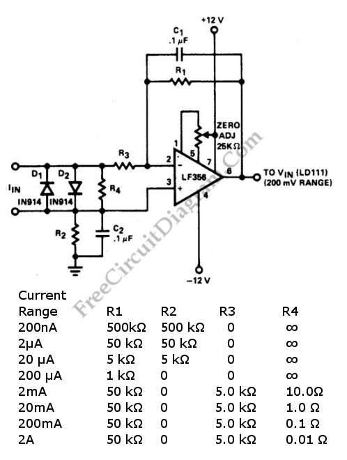
Current to voltage converter circuit can be made using a single resistor, it is very simple since any current will naturally develop a voltage when flow through a resistor. Using an active component, a small developed voltage on a resistor can be accurately measured since we can amplify it to reach a convenient level to be measured. A schematic diagram below shows a current to voltage converter circuit using op-amp as the active component to amplify the signal. This circuit is suitable to be used for digital voltmeter (DVM) set to 200.0 mV range. Using proper resistor value selection, this circuit features eight decades of current range. Here is the schematic diagram of the circuit:

[Circuit' schematic diagram source: seekic.com]
Possibly Related Articles:
- TC9400 Wide Frequency Range Pulse Generator
The reason why TC9400 V/F converter is very useful in the laboratory are because it’s portable, battery-operated, and low cost frequency source. Both pulse and square-wave outputs are provided by... - Photovoltaic (Solar Cell) Current To Voltage Converter
The simplest I to V converter is the humble resistor. However, presenting a nonzero impedance to the source of input current is the disadvantage of the humble resistor. If the... - Current to Voltage Converter
In the simplest form, current to voltage converter can be implemented as simple as one resistor, since a voltage is developed when an electrical current flow against a resistance. The... - Log Converter with 100dB Dynamic Range
This is a circuit of Log Converter with 100dB Dynamic Range. This circuit can give a a logarithmic output voltage for a linear input current. This circuit use an LM108... - PolyPhase DC-DC Converter: Voltage vs Current Mode Control Sharing – Video Tutorial
This is a voltage vs current mode control current sharing in a poly phase DC-DC converter video. This video explains the different of the voltage and current mode control in... - 450W Power Factor Controller with Universal Input Voltage Range
This power factor controller accept voltage from 90 to 268 Vac, that’s why we call it power factor controller with universal input, since any standards of mains supply in almost... - LF356 4-Ranges Ac Millivoltmeter
This is a 4-range AC millivolt meter circuit. This circuit is used to measure a AC voltage in millivolt range. This circuit has frequency response of a few Hz to... - A/D Conversion with Voltage-to-Frequency Converter
To accomplish A/D conversion with V/F converter in a microcontroller system, there are two schemes that can be utilized. First, VIN is measured by counting the FOUT frequency for 1ms,... - Voltage-to-Pulse Duration Converter
This is a circuit of Voltage-to-Pulse Duration Converter. This circuit is used to convert voltage into pulse duration by combining a timer IC and an OP Amp. This circuit can... - Voltage-Current(V/I) Curve Tracer
Voltage-Current curve tracer is very important tools for components ant circuits troubleshooting. This circuit need an oscilloscope with X-Y inputs to display the curve. This circuit provide adjustment for both... - Current Sensing for High Voltage Application
High voltage current sensing/monitoring can be designed using LTC6101 op-amp. The following current sensing circuit is capable of measuring electrical current in 500 volts system. Here is the schematic diagram... - Voltage and Current Limited Audible Continuity Tester
Using this continuity tester circuit, a failure of PCB tracks be examined without looking directly at the tracks routing, which is can be very frustrating. The indication of this circuit...
| 

