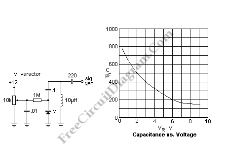
Varactor Test (Experiment) Circuit

A varactor is also known as a varicap or a variable capacitance diode. An electrically controllable capacitance is provided by this varactor which can be used in tuned circuits. What makes it’s advantageous in many application are the small size and inexpensive. If compared to a manually controlled variable capacitor, this varactor has disadvantages such as lower Q, nonlinearity, lower voltage rating and a more limited range. You can find the varactors background material in the reference.
 The schematic diagram above is basic circuit for testing a varactor. 1M resistor that isolates the DC voltage source from the circuit attached to the varactor is the key. The DC bias voltages is blocked by the 0.1 uF capacitor. I happened to have a 10uH inductor in hand, one of those that looks like a fat resistor, and has a reasonably high Q. Through a 220pF capacitor, the RF signal generator was coupled and set for an unmodulated output. We cannot accurately measure the capacitance of the varactor with this circuit because of stray capacitances, but we can certainly see its action.
Another method closely related to the actual application of the varactor was used because the capacitance meter did not give satisfactory results: we can vary the frequency to look for a maximum while observing the voltage across the tuned circuit with an oscilloscope. After getting the resonant frequency, then calculated capacitance is recorded to draw a capacitance versus voltage curve. You will find an nonlinear curve for that, but it means a linear relationship between voltage and frequency.