Variable Frequency Switch Mode Regulator
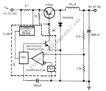
This voltage regulator circuit operates in switch mode. Using the configuration shown in the schematic diagram, this circuit has variable switching frequency, depends on the input voltage and load condition. The core controller of this switching regulator is a TL497 switching regulator controller IC. Here is the schematic diagram of the circuit:
When the load is low (draw only small current), this circuit will lower the frequency to give lower active factor, keeping the output voltage at constant level. When the load draw higher current then this regulator circuit will produce higher switching frequency to compensate the faster drop output capacitor (100uF). You can see that the voltage of this output is sense through voltage divider resistors (3.3k and 1.2k), we can tune this resistor to give other than 5V output voltage. A 75% efficiency is possible to achieve with this switching regulator circuit.