Archive for the ‘Testing and Measurement’ Category
Strobed Supply Improves Strain Gauge Bridge Efficiency

The following schematic diagram shows a method to reduce power consumption without sacrificing the bridge signal output level of a strain gauge. Many situation will be applicable for this strain gauge bridge signal conditioning circuit, where continuous output is not a must. In the long time frame, this circuit will in idle state for almost …[Read More]
Pre-Amplifier Circuit for Oscilloscope

An oscilloscope amplifier with 20 dB voltage gain is provided by this circuit with a frequency range from 0.5 to 50 MHz. By increasing the value of the 0.05 uF capacitor or try removing the capacitor, we can extend the low frequency response of this circuit. A particularly small level of input noise is delivered …[Read More]

A schematic diagram of simple tachometer circuit is shown below. Using only a single transistor as the active component, this tachometer would probably be the simplest one. The input of this circuit can be picked up from ignition pickup coil, or other wiring that gives ignition wave-form. This tachometer circuit works for 0 to 6,000 …[Read More]
Sferic Signal Simulator

Sferic signal simulator is used to produce an impulse signal which simulates the waveform of a sferic, a radio atmospheric signals produced by a lightning strike. In time domain, the waveform of a sferic signal is a single high amplitude spike. When this pulse is analyzed in frequency domain, it will show a wide band …[Read More]
LF356 Wide Range Current-To-Voltage Converter

Current to voltage converter circuit can be made using a single resistor, it is very simple since any current will naturally develop a voltage when flow through a resistor. Using an active component, a small developed voltage on a resistor can be accurately measured since we can amplify it to reach a convenient level to …[Read More]
Capacitor ESR Meter

This is schematic diagram of capacitor ESR meter circuit. ESR is equivalent series resistance, and this parameter is used to express the resistance value of any electronic component that basically is not a resistor. ESR is present on many non-resistor component, such as capacitor, inductor, or semiconductor. The circuit shown in this schematic diagram …
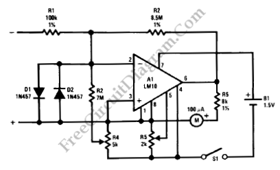
Scope’s Time Base Calibrator

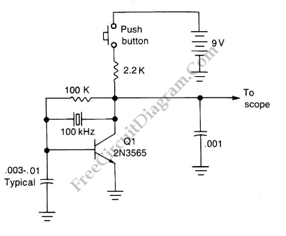
A scope calibrator is a circuit that is used for calibrating the variable time base oscillator of general purpose scopes. This scope calibrator gives 100kHz reference, so if the scope is set to 10 cycles on 10 graticule divisions, then each division represents 10 microseconds or 100kHz. And each division will represent 1 Mhz or …[Read More]
| 

